
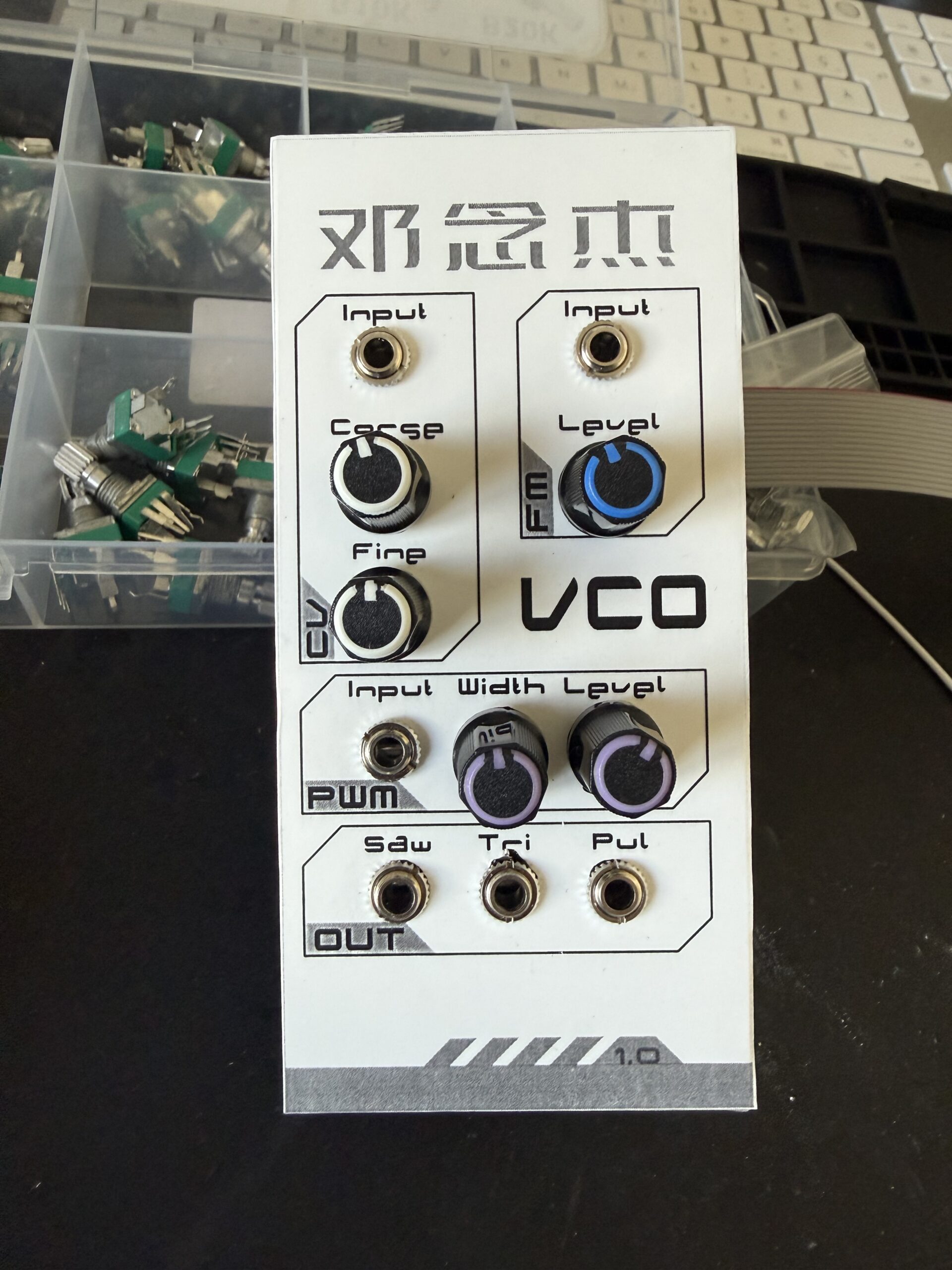
So after a lot of prevaricating and trying to decide do I go with the Kosmo format or Eurorack, I decided on the Eurorack format. I live in a condo building and only have so much space! I also decided to build a VCO as I had been following Moritz Kleins DIY VCO series. If you’re just starting out yourself I strongly recommend it!
I also decided that I’d go with old school thru-hole components. I’m aiming to build something that maps to the old systems of the late 70’s early 80’s so this has determined my build approach.
Having watched the MK series I built a copy of the schematic in KiCad, it ended up looking like this:
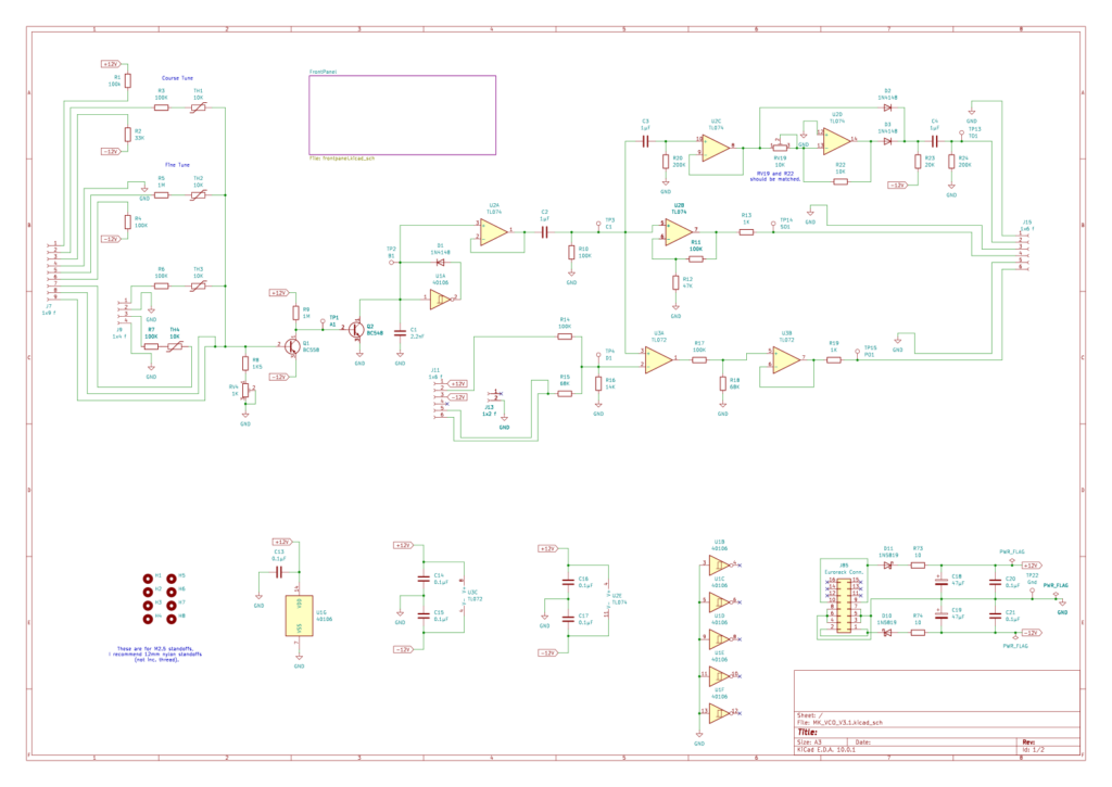
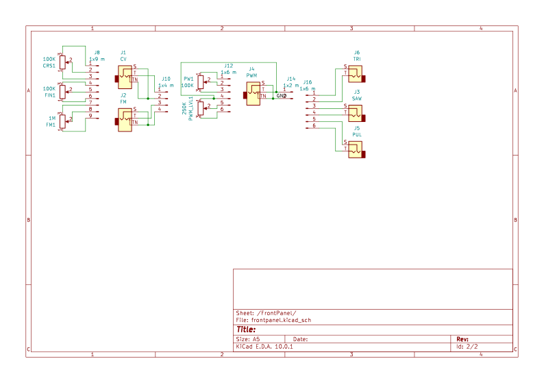
In this design I made the front panel a separate board and used header pins to connect the boards. I also cribbed the power supply design from the Erica Synths design for this board.
To aid really understanding this I got the full EDU DIY Labor kit that Moritz Klein designed so I could bread board this to really get my head round what was going on. This a multimeter and a hand held Oscilloscope I got proved to be invaluable to seeing how this all worked. I find the EDU Labor is still a great tool for testing out other circuit designs.
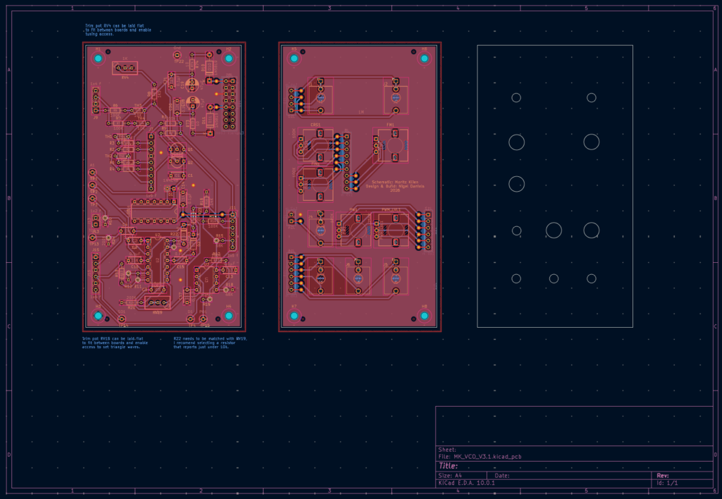
I then had my first go at designing a PCB, I also used the control panel PCB design to map out a front panel layout, for this I just sized the holes based on the components locations, grouped them then dragged them across and drew a new board around them. Note: I forgot it needed to be bigger to form a Eurorack front panel, but it was good enough for this build.
I also found it tricky to ensure the pins and headers were in the correct locations and that they were on the back of the board for the front panel, I also had to place the 16-pin power connector on the back of the main PCB. As I was building this manually I had to figure out how to implement vias. What I did (and still do) is made some large vias that are component leg size, I then solder a component leg on both sides and trim it to make an electrical connection from one side to the other. If any one has a better approach I’d love to know!
So it was onto the build itself, I tried using glossy magazine paper and thermal laser jet transfer and just made a mess, it was terrible. In the end I ordered some Heat Toner Transfer paper and I got a used badge laminator and had way better results. For this first build I then used alignment pins and ferric chloride etching to make the board (you can check out the process in my Notebook).
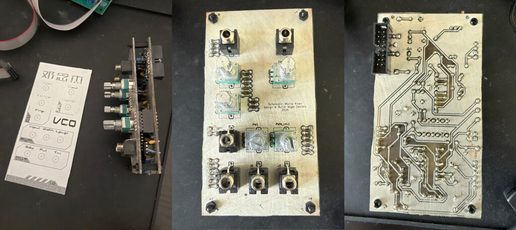
In the end I ordered an aluminium panel for this and then exported an SVG of the layout. I then used Inkscape to design the look of the panel [90’s vectorcore style]. I then manually drilled the holes, so not the most precise 🙁
So here is the final working module, it has some faults, the triangle wave is not the same voltage level as the other outputs, also the sweep of the PWM goes to levels were there is no pulse! However as a first attempt I’m happy and I learned a LOT doing this 🙂
BTW if you’re interested in this module I put the KiCad project up on Github here.
Leave a Reply