
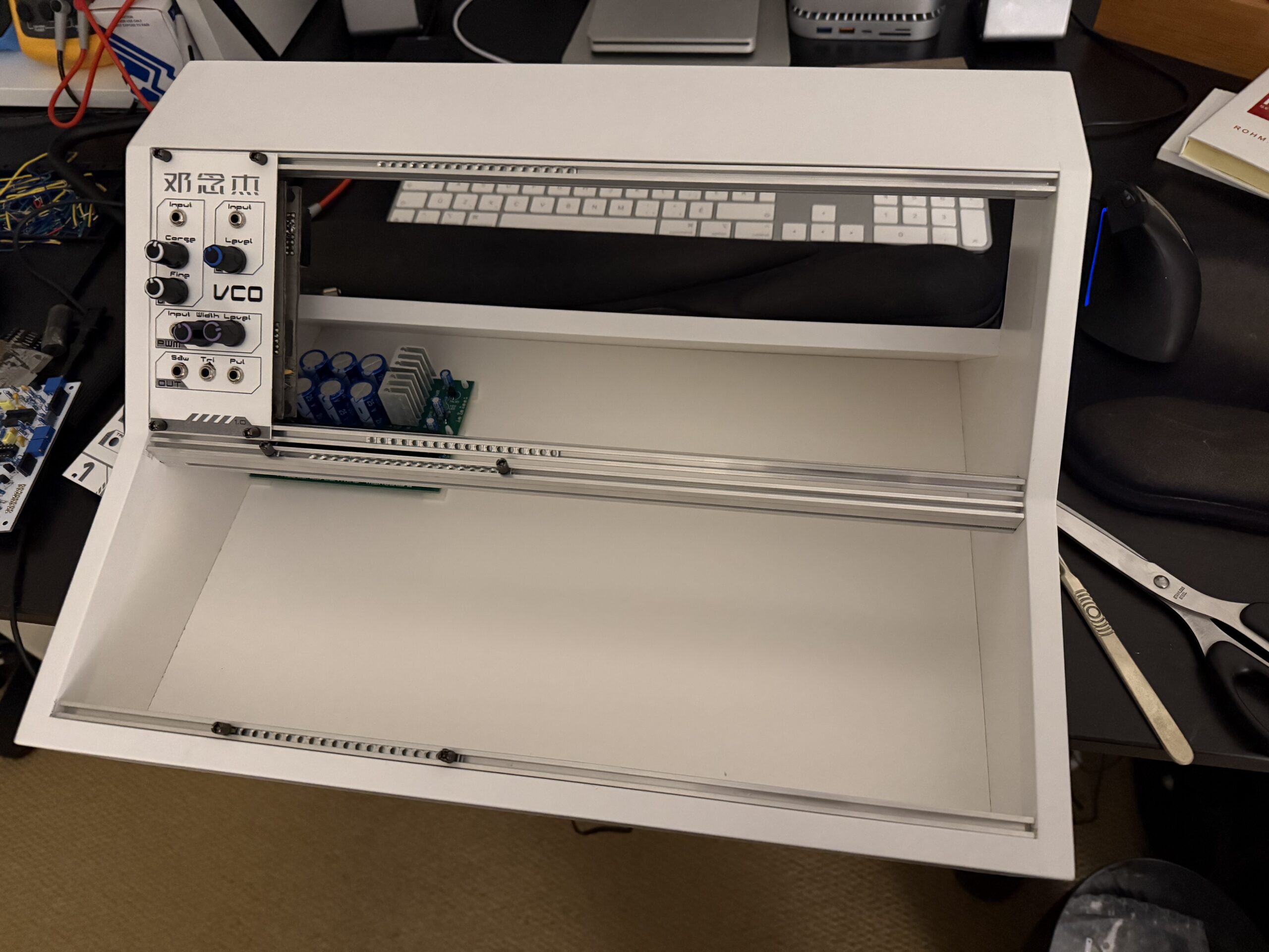
So now I had a module the next this was to build somewhere to put it (and subsequent modules), so I needed a case. While I can design things I am NOT skilled in wood working or similar craft, fortunately my good friend Andrew is and he volunteered to build the case for me. He’s also an electronic engineer and has been super encouraging while I’ve been working on this, he just lent me the Art of Electronics 3rd Ed, quite a tome!
For the design I tried out several CAD systems and eventually settled on OnShape as my CAD tool of choice, for me it had the right balance of ease of use meets feature rich enough to do something serious. It’s also free to use in basic mode so long as you share designs. Even so it took a while to get used to the approach and figuring out you need to start in the parts design before you move to the assembly view was critical.
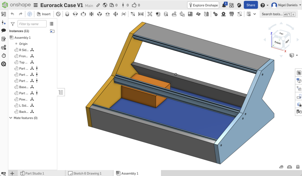
For designing stuff I finally figured out you need to:
- Draw the part in a ‘sketch’.
- Extrude the part to the right thickness.
- Import the part 1 or more times into the assembly window.
- Put everything together.
Once I was happy everything fit together correctly I could then go back to the parts design and for each part generate a drawing file, these I then printed to PDF so I could give Andrew the files with all of the relavent dimensions.
BTW the orange block inside the case is so I could check where the power supply was going to sit. For this I used another Frequency Central board the Microbus. The rails I purchased from Synthrotek, if you use different rails (or PSU) I recommend you copy and modify this design to represent the rails you are using as this could impact the drill holes in the sides. If you do want to reuse this design it’s publicly available on the OnShape site.
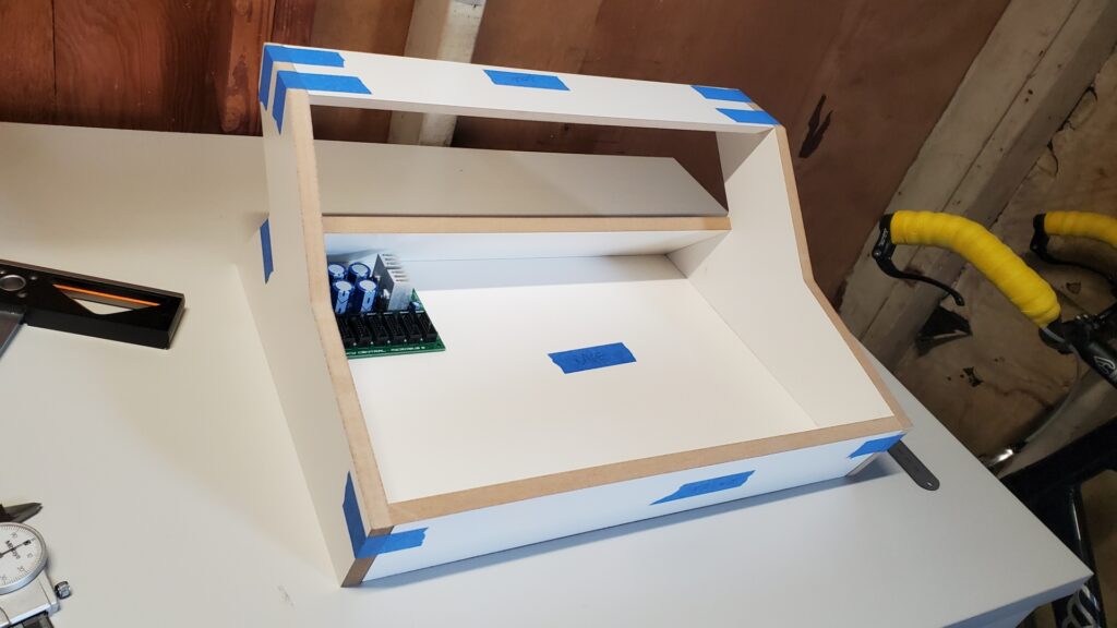
The material I used for the case itself was a sheet of coated MDF I picked up in Ikea’s leftover parts bin, it only cost me $10 and I got a couple of sheets. You can see the first time the case was put together to check the basic dimensions were good above. Here you can also see the unfinished edges of the MDF as Andrews skilled at this stuff and a perfectionist these were covered later.
In the next step he looked at the rail placement and we iterated here a couple of times to ensure there would be enough clearance when modules and screws were in place. Eventually we were happy with the dimensions and he drilled the holes and fit all of the rails.

So here is the finished case with the rails and nuts in place, it was the distance between the two center rails that caused the adjustments. This was taken just before I went round to collect it and I used some adhesive nylon PCB standoffs to hold the power supply in place. So now my modules have a home, I really need to work out if the one PSU will be able to support a fully populated case or if I need to add another and rearrange where they sit.
Leave a Reply